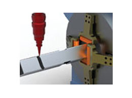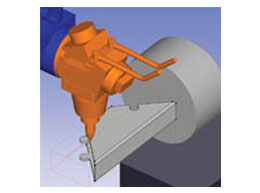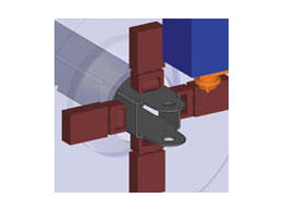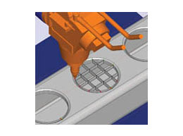
Radtube is an industry leading Laser CAD/CAM system for rotary and multi axis cutting machines developed specifically for tube cutting and manipulation industry. The intuitive programming system allows tubes or sections to be parametrically defined from a library of standard shapes into which cutting apertures and profiles can be defined.
By using Radtube, not only will programming time be minimised, but also the eventual cut-path will be far more efficient, saving further time on the machine. Add in the comprehensive simulation and proofing tools and you have a system that streamlines day-to-day production, reduces costly errors and eradicates the need for dry-runs.
Radtube comes with an extensive range of integrated CAD data translators that allow the direct import of CAD drawings in their native form or as industry standards, such as IGES, STEP and DXF. The standard system configuration comes with interfaces for DXF, AutoCAD DWG, AutoCADInventor, VISI, SolidWorks, SolidEdge, IronCad and Solid IGES. Optional CATIA V4, CATIA V5, Unigraphics, Pro Engineer, VDA and STEP translators are available. Radtube can display the CAD data as simple wireframe, solids and surfaces or a combination of both. Solids are used as the source for all cut-path programming and process simulation.
Radtube contains a comprehensive database of laser machines from a large number of Machine Tool manufacturers; including Adige, NTC, Trumpf and Amada. Should a machine not be supported, Radtube also contains a Machine Setup utility that allows the configuration of bespoke machine types and post processing information. The advanced postprocessors aren't just limited to the use of generic G and M codes; posts are easily configured to suit different head configurations and table sizes.
Radtube supplies a library of parametric tube shapes that simplify the creation of the tube material to be cut. If a suitable section does not exist, the 'Freeform' option is used to create the special shape section. Freeform shape tubes can even be created from one of the libraries of Radtube parametric shapes. If none of these standard shapes are suitable, the user simply draws the section center line profile or outside / inside shape using the integrated CAD tools. All modelling in Radtube is done entirely in 3D.
In a similar way to tube sections, Radtube supplies a library of parametric hole shapes, again with the option to define 'freeform' shapes; so specialist joint features such as duck tails, clips and key holes are easily added. Holes in the tube are created by generating a solid object to represent the shape, which is then extracted from the tube. The solid can pass through all walls or one wall and can pass through the edge of the section creating a gap.
For holes passing through the tube section at a single or compound angle, positioning can be defined at the mid-point of the section or at a position on the top face. For hole shapes that repeat along the tube in a standard pattern, five pattern shapes are supported: Circle, Line at an Angle, Arc, Square and Grid.
Where a number of small parts can be produced from a common tube section, it is possible to use the Radtube nesting option. This allows the user to create individual programs for each part (including cutting path), simulate and check the cutting path. Parts of suitable section are then selected and the quantity required specified. New parts and quantities are added until Radtube reports that the material length specified is full. As each part is selected, Radtube automatically checks the section of the material and reports if it is a suitable part for the nest.
An advanced nesting option is also available which will nest previously machined parts into a multiple number of tubes, where each nested tube can then be postprocessed to form a complete NC program. This advanced nesting functionality provides an easy route to using stock material most effectively and economically.
Within Radtube the toolpaths are presented showing the angle of the nozzle as it moves around the part in a full solid simulation. Instant feedback is provided about whether or not a specific move is possible - either in terms of machine head movement limits or accessibility. Any collisions that are detected are highlighted both on the model and via on-screen messages.
The toolpath parameters can be edited directly or, in the event of a collision, automatically corrected at any time ensuring that your toolpath is both safe and using the optimum strategy to reduce processing time. Once the toolpath has been optimised, simply select the cutting conditions from the pre-defined technology tables and Radtube quickly generates reliable NC code.


